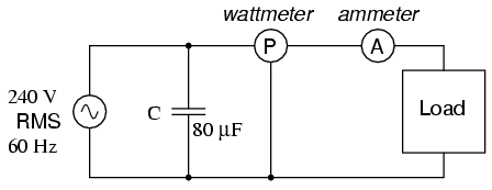
Power Factor Correction Capacitor Circuit
The latest generation of power factor correction equipment uses thyristors to control the current to the capacitor during the charging period the thyristor is controlled by a microprocessor which is integral to the power factor correction unit. The power factor correction calculation assumes inductive load.
Why Current Decreases After Power Factor Correction Quora
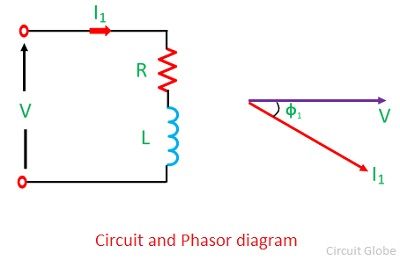
A resistor and inductor in series.

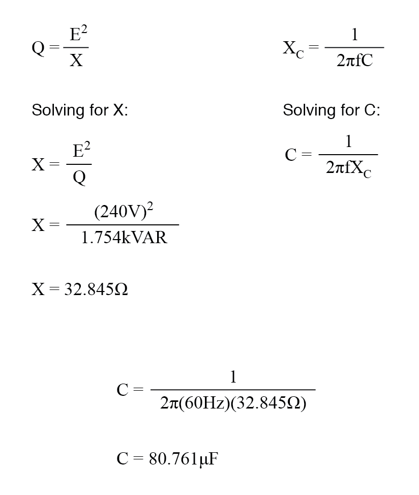
Power factor correction capacitor circuit. Rounding this answer off to 80 uf we can place that size of the capacitor in the circuit and calculate the results. Power factor correction capacitor and electronic means of power factor correction provide well known benefits to electric power systems. The power factor correction means bringing the power factor of an ac circuit nearer to one by using the equipment which absorbs or supply the reactive power to the circuit.
These benefits include power factor correction poor power factor penalty utility bill reductions voltage support release of system capacity and reduced system losses. In this video i describe a simple ac circuit in which a voltage source drives current through an rl load ie. Power factor correction capacitors could be applied to each individual motor to correct the power factor of that motor or could be a single unit connected to the main bus of the switchgear.
The power factor correction capacitor should be connected in parallel to each phase load. Single phase circuit calculation. The power factor calculation does not distinguish between leading and lagging power factors.
Practical power factor correction chapter 11 power factor pdf version. Power factor correction objective. In the latter case the unit should have power factor sensing circuits that automatically determine the amount of capacitance required for maintaining a preset power factor.
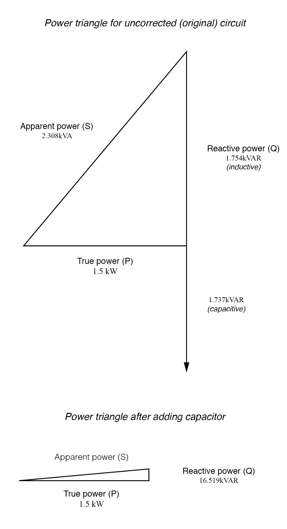
Power factor correction circuits are used to minimize reactive power and enhance the efficiency with which inductive loads consume ac power. Usually the power factor correction can be done by using the capacitor and the synchronous motor in the circuitthe power factor correction will not change the amount of true power but it will reduce the apparent power and the total current drawn from the load. Figure below parallel capacitor corrects lagging inductive load.
Power factor correction circuit optimization within the modern smps switch mode power supply units could evolve in the recent past due to the advent of a number of advanced relevant integrated circuits ics which has made possible to lay down different pfc designs having specific modes of operation and with individual challenge handling capability. I derive an expression for c the capacitance. Capacitors are essential components in power factor compensation circuits and this article will explore some design considerations when using these components for power factor correction.
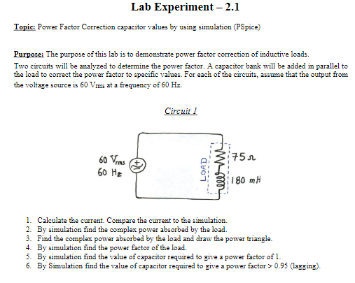
Solved Lab Experiment 2 1 Topic Power Factor Correctio
People Say That If We Add Enough Power Factor Correction

Figure 3 From Implementation Of Power Factor Correction

Circuitry For Power Factor Improvement By Capacitors

Designing A Power Factor Correction Circuit

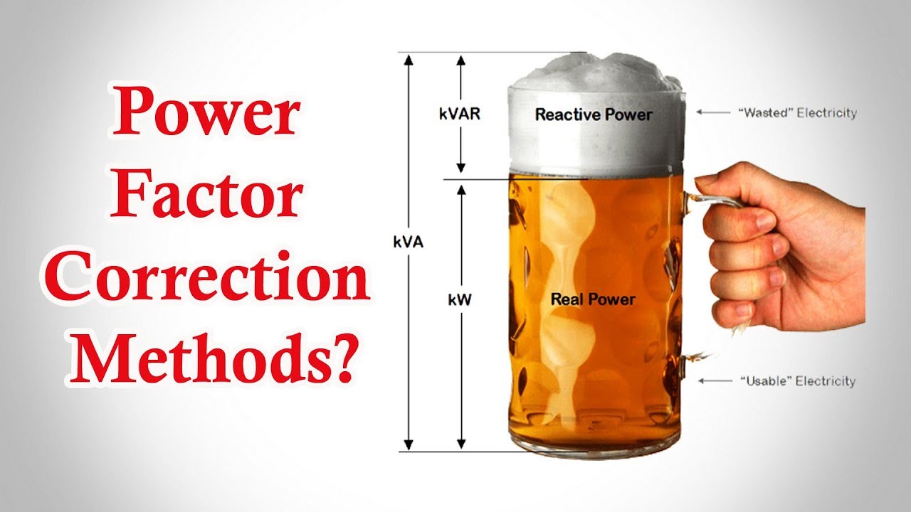
Power Triangle And Power Factor In Ac Circuits
Why Is Capacitor Placed In Parallel For Power Factor
Power Factor Correction Power Factor Correction Methods Power Factor

Power Factor Correction Power Quality Captech
Power Factor Correction By Static Capacitors Circuit Globe

What Is Power Factor Correction Energyace

Charged Evs A Closer Look At Power Factor Correction
Automatic Power Factor Correction Apfc Using Microcontroller
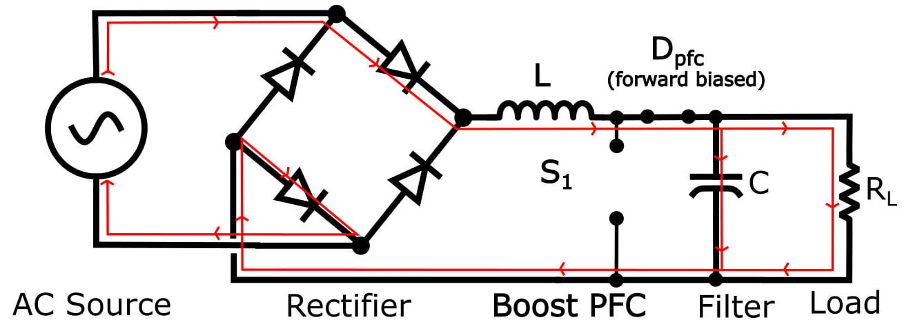
How The Boost Pfc Converter Circuit Improves Power Quality
Practical Power Factor Correction Power Factor
Practical Power Factor Correction Power Factor
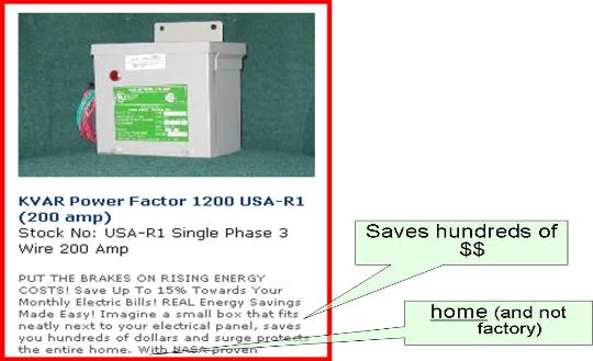
Kvar Power Factor Correction In The Home Is A Scam
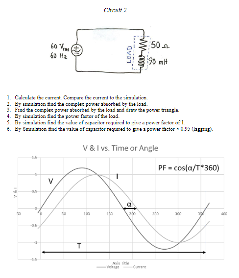
Solved Lab Experiment 2 1 Topic Power Factor Correctio
Practical Power Factor Correction Power Factor

Post a Comment for "Power Factor Correction Capacitor Circuit"